|
Power Factor Control Relay
BLR-CA
Technology of the BLR-CA Relay
Evaluation of the reactive load is achieved by taking instantaneous measurements in all four quadrants of voltage and current. These values are digitalised in the microprocessor and continuously evaluated so as to provide the active and reactive components. The value of cos phi is calculated from these two values. If the actual reactive load deviates from the target power factor, then a 'trial switching' will be made on the as yet 'unknown Capacitor Step Values'. The first process on new installations is a 'learning curve' of the value of each capacitor in the process of normal switching. It is no longer necessary to manually select the starting current - or C/k value. The value of each capacitor step will be evaluated by the relay and stored in its memory permanently, even if the voltage supply to the relay fails. Any subsequent loss of reactive power from any capacitor step will be recognised and evaluated. Total loss of reactive step output due to fuse failure for example, will be recorded in the relay memory as a defective step.
The relay will select from the bank of capacitors available the step(s) which are necessary in order to achieve the required level of reactive compensation. Switching exits which are not connected or defective capacitor steps (failed fuse for example) will be excluded from the regulation process. At weekly intervals, or each time the relay is re-energised, three attempts will be made to check any previously reported failed capacitor step. If the fuses have been replaced for example that step can then be brought back into the reactive compensation calculation.
The recognition of the value of each capacitor step is achieved without unnecessary test switchings - based on those obtained in the daily routine of reactive load compensation. Fixed switching programmes are no longer required. The relay will automatically select from its memory the most appropriate capacitor step size to meet the reactive load demand.
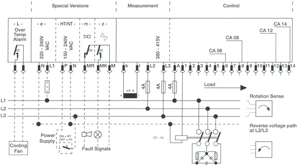
There are four different types of the BLR-CA relay: BLR-CA 06, 08,12,14 with 6, 8,12 or 14 switched steps. If all steps are not required, a step limiting feature can be programmed on site.
Target Power Factor Setting
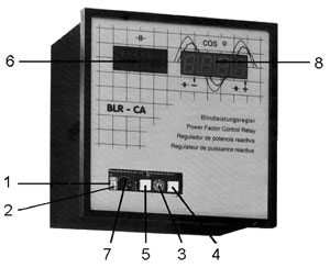
The target power factor setting is adjusted using function switch (3) located behind the nameplate cover. In position 1, the target cos phi can be precisely selected on the digital display using the +/-buttons (4 and 5).
Step Switching Time
The time delay per step is selected using function switch (3) in position 2. Using the +1- buttons the precise switching time can be selected on the digital display within the range 5 ... 1200 sec. For normal installations the switching time should not be less than 20 seconds per step.
Shorter switching times can be selected when required. This is made possible by means of an integrated reac-tive load reversal switching delay feature. This will pro-vide an additional 30 sec. delay before any step which has just been switched off can be switched back on again. However, it must always be born in mind that shorter switching times will result in a higher switching rate and consequent wear on contactors etc.
Digital cos phi Indication
With function switch (3) in position 3, in addition to regulating the reactive load the digital indicator will show the instantaneous value of the system power factor. This is achieved by calculating the relationship between active and reactive load - a feature which is becoming even more important due to the normal occurrence of non-sinusoidal waveforms.
Switching by Hand
With function switch (3) in position 4, capacitor steps can be switched in and out according to the selected switching time delay, using the +1- buttons. Only one depression is necessary. Once the required switching is achieved the next command is given.
To return to automatic control, switch (3) must be returned to position 3. The function switch is in this position on delivery of the relay.
No-Volt Release Feature
In the event of a power failure longer than 35 msec., the relay will immediately disconnect all capacitors from the supply. Once the supply is restored, there will be lockout time of 90 sec. before the relay starts switching.
This lock out time will also apply on initial energizing of a new installation.
LED Indication of Capacitor Steps
The LED display (6) will show the status of each capacitor step.
Data Link and Printer Port
A miniprinter or UMS data link (TTLRS 232) can be connected for system diagnosis at socket (7), located behind the nameplate.
This will record all switching operations, together with system power factor, date, time, fault signalling alarm operation, no-volt release operation, as well as change overs to Hand/Automatic (Miniprinter details in catalogue sheet 'Compensation Analyser' KA 02).
Internal Fault Signalling
The BLR-CA relay incorporates a fault signalling alarm which will indicate, for example, if there are insufficient capacitors to achieve the target power factor. The letters 'AL' will appear in the display, if DIP switch (2) is in the 'ON' position (up). The alarm will be indicated after a time delay of 75 times step switching time.
Position 9 of the function selection switch is used to select whether the alarm operation is stored until cancelled (display '0') or cancelled automatically once the power factor improves to the target level (display 'I'). The required selection is made by means of the +1- buttons. Moving DIP switch 2 to the 'OFF' position will delete the recorded fault signal alarm.
|
 BLR-CB Brochure BLR-CB Brochure
Standard Features
Power Factor Correction
Automatic Self Adjustment to any Capacitor Step Value
Digital Indication of Power Factor, pre-set Parameters and specified Installation Data
No-Volt Release Feature to immediately Disconnect all Capacitors in the Event of Power Failure
Facility to Connect Miniprinter
Plug-in Terminal Connection
Digital Setting of Individual Parameters including Target Power Factor, Switching Time, Step Limit, etc.
Elimination of Defect Capacitor Steps, and their Indication (e.g. Welded Contactors)
Visual Display of Target cos phi Alarm
Visual Display of Harmonic Overload Alarm (du/dt)
Optional Features
Second Target Power Factor Setting for Off Peak Tariffs
Asymmetric Switching Times
Reactive Load Reversal Switching Time Delay for Rapid Switching Times
Remote Indication of cos phi
Fault Signalling Contact (m) to Indicate Target cos phi Not Obtained
Fault Signalling Contact (z) to Indicate Overloaded Capacitors due to Harmonic Waveform
Power Factor Correction
Capacitor Harmonic Surveillance
All BLR-CA relays are fitted with a specially developed harmonic surveillance device which will oversee the voltage dynamic du/dt. The measured voltage is reviewed with respect to its deviation from a pure sine waveform. Since Capacitor current is heavily influenced by the dynamic of the supply voltage, the total effect is evaluated by measuring the current. If this current exceeds its nominal value by approx. 120% over a time interval of 1 minute (current-time measurement), then the symbol 'HA' will appear in the display. This alarm can be coupled to an exit relay 'z' which will provide an external alarm signal of Harmonic Overload on the capacitor bank. This device requires the exact determination of the operation frequency 50 or 60 cps (to be stated in order).
Optional Features - Power Factor Correction
Fault Signalling Contact (m)
for External Signalling (cos ~)
An additional relay (m) can be fitted which will provide an extremely worthwhile additional feature to any Power Factor Correction Installation. In the event of over - or under - compensation in relation to the target power factor, after a period of 75 times the selected step switching time, the relay contact will close. This can energize an acoustic or visual external alarm.
If an external voltage source is available, this relay will also report if the power supply is lost to the capacitor bank. This feature enables the relay to provide an early report of insufficient installed capacitance, or capacitor, fuse or contactor failure. This is far more cost effective than waiting until excessive reactive current costs appear on the electricity bill.
Harmonic Overload Fault Signalling Relay (z)
As a supplement to the capacitor control function du/dt, for harmonic current overload and in addition to the visual alarm 'HA' in display (8), the external fault signalling relay (z) can be fitted for remote communication of a fault signal. Volt-free contacts 1500 VN250 V AC.
Connection to a PC
All the data transmitted to the printer port can be stored on a PC having a standard VGA graphics adapter, using the 'BLR' software and the UMS interface, which is fitted separately. The following data can be recorded and stored: Power factor, contactor switching functions, alarm functions ('AL', 'HA' or 'AH', if triggered both), no-volt release operation, time, date, Hand/Automatic change-overs, a summary of capacitor step switchings for each step and each day.
Remote Indication of Power Factor Cos phi (F)
This supplementary device, order reference DCA-F, offers remote transmission of the digital power factor display on to a 96 x 96 mm digital display panel mounting instrument. This remote indicator can be up to 250 mtrs distant and connections should be made with coaxial screened cable.
Cos phi Change-Over High/Low Tariff Settings (TN)
With function switch (3) in position A it is possible to set a second target power factor for the low tariff period. This second value is activated by means of a signal voltage (250 V AC max.) via time clock or electricity supply company impulse applied to an additional five pole terminal plug L1/N on the back of the relay. If there is no voltage applied across L1/N then the first target power factor for compensation will be active as in position 1 on the function switch.
|